

Pacemaker is the standard cluster resource manager on RHEL, working with Corosync for cluster communication. Together they provide automated failover, resource management, and health monitoring for critical services.
This article will help you learn how to setup/configure a High-Availability (HA) cluster on RHEL/AlmaLinux based systems. In our setup, we will be focusing on High-Availability (Active-passive) also known as Fail-over cluster. One of the biggest achievements by having the nodes in the HA cluster will be tracking each other’s nodes and migrating the service/application to the next node in-case of any failures in the nodes. Also, the faulty node won’t be visible to the clients from outside, but there will be a small service disruption during the migration period. It also maintains the data integrity of the service using HA.
The High-Availability Pacemaker Cluster in RedHat / AlmaLinux / RockyLinux is completely different from the previous versions. In RedHat version 7 onwards “pacemaker” becomes the default Cluster Resource-Manager (RM) and Corosync is responsible for exchanging and updating cluster information with other cluster nodes regularly. Both Pacemaker and Corosync are very powerful open source technologies that are completely the replacement of CMAN and RGManager from the previous versions of RedHat clusters.
This step-by-step guide will help you on how to configure a High-Availability (HA) / Fail-over Pacemaker cluster with common ISCSI shared storage on RHEL/AlmaLinux / RockyLinux . You can use the same guide for all the versions with a few minimal changes.
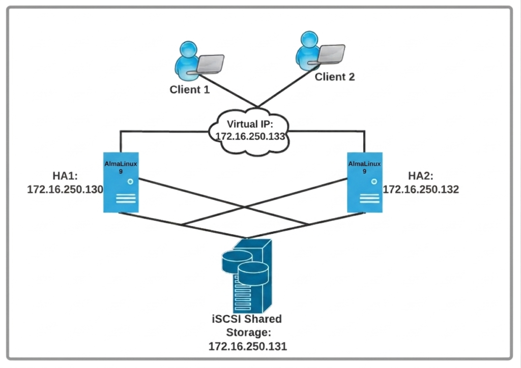
Pacemaker High Availability Cluster Architecture
Prerequisites:
Operating System : RHEL, AlmaLinux
Storage : iSCSI SAN
Floating IP address
Network connectivity between nodes
For Cluster nodes package : pcs, fence-agents-all and targetcli
My Lab Setup :
For the lab setup, I am using 3 AlmaLinux Machines. Two for Pacemaker Cluster nodes and one for ISCSI/Target Server
Node-1:
 Operating System:- AlmaLinux 9 hostname:- gk.node1 IP Address:- 172.16.250.130
Node-2:
 Operating System:- AlmaLinux 9 hostname:- gk.node2 IP Address:- 172.16.250.132
ISCSI - Server:
Operating System:- AlmaLinux 9 hostname:- iscsi-gk.node IP Address:- 172.16.250.131 Block device :- /dev/sdb
Other Info:
Cluster Name :- linuxgktech-cluster Virtual IP:- 172.16.250.133
Step 1: Setup Storage Server (iSCSI)
Use the following command to check the available block device to use for a Storage Server.
[gk@localhost ~]$ lsblk
NAME               MAJ:MIN RM  SIZE RO TYPE MOUNTPOINTS
sr0                 11:0    1 1024M  0 rom
nvme0n1            259:0    0   15G  0 disk
├─nvme0n1p1        259:1    0  600M  0 part /boot/efi
├─nvme0n1p2        259:2    0    1G  0 part /boot
└─nvme0n1p3        259:3    0 13.4G  0 part
  ├─almalinux-root 253:0    0 11.9G  0 lvm  /
  └─almalinux-swap 253:1    0  1.5G  0 lvm  [SWAP]
nvme0n2            259:4    0    5G  0 disk
From the above command, it will list all (nvme0n1 and nvme0n2) the block devices in a tree format. In our demo, I will be using “/dev/nvme0n2” with 5 GB disk as shared storage for cluster nodes.
Add the following entries into /etc/hosts file in the following format “IP Address Domain-name”. This will help resolve host-names, which means it can easily bind local IP addresses into a host name, web address, or URLs.
[root@iscsi-gk ~]# echo "172.16.250.131 iscsi-gk.node" >> /etc/hosts
Now update to the latest current version and then install the target utility package with followings comman.
dnf update -y
dnf install targetcli -y
Now follow the below command to get into the interactive shell of the iSCSI Server.
[root@iscsi-gk ~]# targetcli
targetcli shell version 2.1.57
Copyright 2011-2013 by Datera, Inc and others.
For help on commands, type 'help'.

/>
1. Create a backstore block device:
/> /backstores/block create gktechlun1 /dev/nvme0n2
2. Create iSCSI for IQN target:
/> iscsi/ create iqn.2026-05.local.server-iscsi:server
3. Create ACLs:
/> iscsi/iqn.2026-05.local.server-iscsi:server/tpg1/acls create iqn.2026-05.local.client-iscsi:client1
4. Create LUNs under the ISCSI target:
/> /iscsi/iqn.2026-05.local.server-iscsi:server/tpg1/luns create /backstores/block/gktechlun1
5. Enable CHAPP Authentication:
/> cd /iscsi/iqn.2026-05.local.server-iscsi:server/tpg1/
/iscsi/iqn.20...i:server/tpg1> set attribute authentication=1
Parameter authentication is now '1'.
/iscsi/iqn.20...i:server/tpg1> cd acls/iqn.2026-05.local.client-iscsi:client1/
/iscsi/iqn.20...iscsi:client1> set auth userid=gktech
Parameter userid is now 'gktech'.
/iscsi/iqn.20...iscsi:client1> set auth password=goodpassword
Parameter password is now 'goodpassword'.
/iscsi/iqn.20...iscsi:client1> cd /
/> ls
o- / .................................................................................................. [...]
  o- backstores ....................................................................................... [...]
  | o- block ........................................................................... [Storage Objects: 1]
  | | o- gktechlun1 ............................................ [/dev/nvme0n2 (5.0GiB) write-thru activated]
  | |   o- alua ............................................................................ [ALUA Groups: 1]
  | |     o- default_tg_pt_gp ................................................ [ALUA state: Active/optimized]
  | o- fileio .......................................................................... [Storage Objects: 0]
  | o- pscsi ........................................................................... [Storage Objects: 0]
  | o- ramdisk ......................................................................... [Storage Objects: 0]
  o- iscsi ..................................................................................... [Targets: 1]
  | o- iqn.2026-05.local.server-iscsi:server ...................................................... [TPGs: 1]
  |   o- tpg1 ................................................................... [no-gen-acls, auth per-acl]
  |     o- acls ................................................................................... [ACLs: 1]
  |     | o- iqn.2026-05.local.client-iscsi:client1 ............................ [1-way auth, Mapped LUNs: 1]
  |     |   o- mapped_lun0 ..................................................... [lun0 block/gktechlun1 (rw)]
  |     o- luns ................................................................................... [LUNs: 1]
  |     | o- lun0 ...................................... [block/gktechlun1 (/dev/nvme0n2) (default_tg_pt_gp)]
  |     o- portals ............................................................................. [Portals: 1]
  |       o- 0.0.0.0:3260 .............................................................................. [OK]
  o- loopback .................................................................................. [Targets: 0]
/> saveconfig
Last 10 configs saved in /etc/target/backup/.
Configuration saved to /etc/target/saveconfig.json
6. Add a firewall rule to permit iscsi port 3260 OR disable it:
[root@iscsi-gk ~]# firewall-cmd --permanent --add-port=3260/tcp
success
[root@iscsi-gk ~]# firewall-cmd --reload
success
[root@iscsi-gk ~]# firewall-cmd --list-all
7. Disable the SELinux with following commands but it is temporary way to bypass SELinux as in Permissive mode it will not block anything just generate error so if you want to disable it complete you can set it in /etc/selinux/config file as SELINUX=disabled
[root@iscsi-gk ~]# getenforce
Enforcing
[root@iscsi-gk ~]# setenforce 0
[root@iscsi-gk ~]# getenforce
Permissive
8. Finally, enable and start the iSCSI target.
[root@iscsi-gk ~]# systemctl enable target.service
Created symlink /etc/systemd/system/multi-user.target.wants/target.service → /usr/lib/systemd/system/target.service.
[root@iscsi-gk ~]# systemctl start target.service
[root@iscsi-gk ~]# systemctl status target.service
● target.service - Restore LIO kernel target configuration
     Loaded: loaded (/usr/lib/systemd/system/target.service; enabled; preset: disabled)
     Active: active (exited) since Fri 2026-05-29 16:08:02 IST; 5s ago
    Process: 52241 ExecStart=/usr/bin/targetctl restore (code=exited, status=0/SUCCESS)
   Main PID: 52241 (code=exited, status=0/SUCCESS)
        CPU: 115ms

May 29 16:08:02 iscsi-gk.node systemd[1]: Starting Restore LIO kernel target configuration...
May 29 16:08:02 iscsi-gk.node systemd[1]: Finished Restore LIO kernel target configuration.
Step 2: Setup Pacemaker High-Availability (HA) Cluster
Add the following host entries to all the nodes and shared storage in the cluster. It will help the systems to communicate with each other using hostnames.
echo "172.16.250.130   gk.node1  gk1" >> /etc/hosts
echo "172.16.250.132   gk.node2  gk2" >> /etc/hosts
echo "172.16.250.131   iscsi-gk.node  iscsi" >> /etc/hosts
(a) Import the LUNs on all the nodes across the cluster (Node1 and Node2)
(i) Before importing LUN from the shared storage, let’s update the latest current version of AlmaLinux release 9.7 on both nodes (Node1 and Node2) and then Install the iscsi-initiator package on both nodes.
dnf update -y
dnf install -y iscsi-initiator-utils
(ii) Use the following command to add the initiator name on both nodes (Node1 and Node2). You can pick the initiator name from the target server which was already created, in our case it is “iqn.2020-01.local.client-iscsi:client1”.
vi /etc/iscsi/initiatorname.iscsi
InitiatorName=iqn.2026-05.local.client-iscsi:client1
(iii) Save and restart the iscsid service on both nodes.
systemctl restart iscsid.service
systemctl enable iscsid.service
systemctl status iscsid.service
(iv) Next, configure CHAP authentication on both nodes (Node1 and Node2)
node.session.auth.authmethod = CHAP
node.session.auth.username = gktech
node.session.auth.password = goodpassword
(v) Now is the time to Discover the iSCSI Shared Storage (LUNs) on both nodes (Node1 and Node2)
[root@gk ~]# iscsiadm --mode discoverydb --type sendtargets --portal 172.16.250.131 --discover
172.16.250.131:3260,1 iqn.2026-05.local.server-iscsi:server
The LUN was successfully discovered on both nodes (iQNs) as we received correct output.
vi) Now use the following command to log in to the Target Server:
iscsiadm -m node --login
Output:
Login to [iface: default, target: iqn.2026-05.local.server-iscsi:server, portal: 172.16.250.131,3260] successful.
(vii) Use the following command to verify the newly added disk on both nodes.
[root@gk ~]# lsblk
NAME        MAJ:MIN RM  SIZE RO TYPE MOUNTPOINTS
sda           8:0    0    5G  0 disk
sr0          11:0    1 1024M  0 rom
nvme0n1     259:0    0 19.5G  0 disk
├─nvme0n1p1 259:1    0  200M  0 part /boot/efi
├─nvme0n1p2 259:2    0    1G  0 part /boot
└─nvme0n1p3 259:3    0 18.3G  0 part /
You can see sda 5GB disk added in both nodes.
(viii) Use the following command to create a filesystem for the newly added block device (/dev/sda) to any one of your nodes, either node1 or node2. I will use it in our demo on Node1.
[root@gk ~]# mkfs.xfs /dev/sda
meta-data=/dev/sda               isize=512    agcount=4, agsize=327680 blks
         =                       sectsz=512   attr=2, projid32bit=1
         =                       crc=1        finobt=1, sparse=1, rmapbt=0
         =                       reflink=1    bigtime=1 inobtcount=1 nrext64=0
data     =                       bsize=4096   blocks=1310720, imaxpct=25
         =                       sunit=0      swidth=0 blks
naming   =version 2              bsize=4096   ascii-ci=0, ftype=1
log      =internal log           bsize=4096   blocks=16384, version=2
         =                       sectsz=512   sunit=0 blks, lazy-count=1
realtime =none                   extsz=4096   blocks=0, rtextents=0
For testing purposes, use the following steps to mount the newly added disk temporarily with /mnt directory and create 3 files named “file1,file2,file3”, then use ‘ls’ command to verify these files are placed in /mnt directory and finally unmount the /mnt directory from Node1.
[root@gk ~]# mount /dev/sda /mnt

[root@gk ~]# df -Th
Filesystem     Type      Size  Used Avail Use% Mounted on
devtmpfs       devtmpfs  4.0M     0  4.0M   0% /dev
tmpfs          tmpfs     477M     0  477M   0% /dev/shm
tmpfs          tmpfs     191M  8.7M  182M   5% /run
efivarfs       efivarfs  256K   37K  220K  15% /sys/firmware/efi/efivars
/dev/nvme0n1p3 xfs        19G  1.2G   18G   7% /
/dev/nvme0n1p2 xfs       960M  204M  757M  22% /boot
/dev/nvme0n1p1 vfat      200M  7.8M  193M   4% /boot/efi
tmpfs          tmpfs      96M     0   96M   0% /run/user/1000
/dev/sda       xfs       5.0G   68M  4.9G   2% /mnt
[root@gk ~]# cd /mnt/

[root@gk mnt]# touch file1 file2 file3

[root@gk mnt]# ls
file1  file2  file3

[root@gk mnt]# cd

[root@gk ~]# umount /mnt/
Now, move on to Node2 and run the following command to see if those files created on Node1 are available on Node2.
[root@gk ~]# mount /dev/sda /mnt/
[root@gk ~]# cd /mnt/
[root@gk mnt]# ls
file1  file2  file3

[root@gk mnt]# cd
[root@gk ~]# umount /mnt
(b) Install and configure Pacemaker Cluster Setup
(i) Use the following command to Install cluster Packages (pacemaker) on both nodes (Node1 and Node2). In case AlmaLinux we need to enable repo highavailability.
dnf config-manager --set-enabled highavailability
dnf install pcs fence-agents-all -y
Once you have successfully installed the packages on both nodes, then configure the firewall service to permit the High-Availability application to have a direct connection between the nodes (Node1 and Node2). If you wish not to apply any firewall rules, then simply disable it.
firewall-cmd --permanent --add-service=high-availability
firewall-cmd --reload
firewall-cmd --list-all
(ii) Now, start the cluster service and enable it for every reboot on both nodes (Node1 and Node2).
 systemctl start pcsd
 systemctl enable pcsd
 systemctl status pcsd
(iii) Cluster Configuration -: Use the following command to set the password for “hacluster” user on both nodes (Node1 and Node2).
echo <EnterYourPassword> | passwd --stdin hacluster
(iv) Use the following command to authorize the nodes. Execute it to only one of your nodes in the Cluster. In our case, I would prefer to run it on Node1.
[root@gk ~]# pcs host auth gk.node1 gk.node2 -u hacluster -p agoodpassword
gk.node1: Authorized
gk.node2: Authorized
The above command is mainly used to authenticate the pcs to the pcsd across the nodes in the cluster. The Token (Authorization) key file will be saved on either one of the paths (~/.pcs/tokens or /var/lib/pcsd/tokens).
(v) Start and configure Cluster Nodes. Execute the following command to only one of your nodes. In our case, Node1.
pcs cluster setup --start --enable gktech_cluster gk.node1 gk.node2

gk.node1: successful distribution of the file 'corosync.conf'
gk.node2: successful distribution of the file 'corosync.conf'
Cluster has been successfully set up.
Enabling cluster on hosts: 'gk.node1', 'gk.node2'...
gk.node2: Cluster enabled
gk.node1: Cluster enabled
(vi) Enable the Pacemaker Cluster service for every reboot.
[root@gk ~]# pcs cluster enable --all
gk.node1: Cluster Enabled
gk.node2: Cluster Enabled
(vii) Use the following command to get the simple or detailed cluster status.
[root@gk ~]# pcs cluster status
Cluster Status:
 Cluster Summary:
   * Stack: corosync (Pacemaker is running)
   * Current DC: gk.node1 (version 2.1.10-2.el9-5693eaeee) - partition with quorum
   * Last updated: Fri May 29 16:25:29 2026 on gk.node1
   * Last change:  Fri May 29 16:20:23 2026 by hacluster via hacluster on gk.node1
   * 2 nodes configured
   * 0 resource instances configured
 Node List:
   * Online: [ gk.node1 gk.node2 ]

PCSD Status:
  gk.node1: Online
  gk.node2: Online
Above command list only the status of your Pacemaker cluster part and the following command will get you the detailed information of the Pacemaker Cluster which consists of the details of the Nodes, the status of pcs and the resources.
[root@gk ~]# pcs status
Cluster name: gktech_cluster

WARNINGS:
No stonith devices and stonith-enabled is not false
error: Resource start-up disabled since no STONITH resources have been defined
error: Either configure some or disable STONITH with the stonith-enabled option
error: NOTE: Clusters with shared data need STONITH to ensure data integrity
error: CIB did not pass schema validation
Errors found during check: config not valid

Cluster Summary:
  * Stack: corosync (Pacemaker is running)
  * Current DC: gk.node1 (version 2.1.10-2.el9-5693eaeee) - partition with quorum
  * Last updated: Fri May 29 16:26:50 2026 on gk.node1
  * Last change:  Fri May 29 16:20:23 2026 by hacluster via hacluster on gk.node1
  * 2 nodes configured
  * 0 resource instances configured

Node List:
  * Online: [ gk.node1 gk.node2 ]

Full List of Resources:
  * No resources

Daemon Status:
  corosync: active/enabled
  pacemaker: active/enabled
  pcsd: active/enabled
We can see that the Pacemaker Cluster setup is working perfectly on both of the nodes, but no resources are configured yet. So, let’s try to add a few resources in order to complete the cluster setup. Before moving forward let us try to verify the cluster configuration.
root@gk ~]# crm_verify -L -V
error: Resource start-up disabled since no STONITH resources have been defined
error: Either configure some or disable STONITH with the stonith-enabled option
error: NOTE: Clusters with shared data need STONITH to ensure data integrity
error: CIB did not pass schema validation
Errors found during check: config not valid
Fencing, also known as STONITH “Shoot The Other Node In The Head”, is one of the important tools in the cluster which can be used to safeguard the data corruption on the shared storage. Fencing plays a vital role when the nodes are not able to talk to each other. This will detach the shared storage access from the faulty node. There are two types available in Fencing: Resource Level Fencing and Node Level Fencing.
For this demo, I am not going to run Fencing (STONITH), as our machines are running in a VMware environment, which doesn’t support it, but for those who are implementing in a production environment please click here to see the entire setup of fencing
Use the following command to disable the STONITH and ignore the quorum policy and check the status of Cluster Properties to ensure both are disabled:
[root@gk ~]# pcs property set stonith-enabled=false
[root@gk ~]# pcs property set no-quorum-policy=ignore
[root@gk ~]# pcs property list
Deprecation Warning: This command is deprecated and will be removed. Please use 'pcs property config' instead.
Cluster Properties: cib-bootstrap-options
  cluster-infrastructure=corosync
  cluster-name=gktech_cluster
  dc-version=2.1.10-2.el9-5693eaeee
  have-watchdog=false
  no-quorum-policy=ignore
  stonith-enabled=false
[root@gk ~]# crm_verify -L -V
[root@gk ~]#
(ix) Resources / Cluster Services
For Pacemaker Clustered services, the resources would be either a physical hardware unit such as disk drive or logical units like IP address, Filesystem or applications. In a cluster, a resource can run only on a single node at a time. In our demo we will be using the following resources:
Httpd Service IP Address Filesystem
First, let us install and configure the Apache server on both nodes (Node1 and Node2). Follow these steps:
dnf install httpd -y
Add the below entries at the end of the apache configuration file (‘/etc/httpd/conf/httpd.conf’)
# vi /etc/httpd/conf/httpd.conf
<Location /server-status>
    SetHandler server-status
    Require local
</Location>
In order to store Apache files (HTML/CSS) we need to use our centralized storage unit (i.e., iSCSI server). This setup only has to be done in one node. In our case, Node1.
mount /dev/sda /var/www/
mkdir /var/www/html
echo "Red Hat Hight Availability Cluster on GKLinuxTech" > /var/www/html/index.html
umount /var/www/
Use the following command to add a firewall rule for apache service on both nodes (Node1 and Node2) OR simply disable the Firewall.
 firewall-cmd --permanent --add-port=80/tcp
 firewall-cmd --permanent --add-port=443/tcp
 firewall-cmd --reload
 firewall-cmd --list-all
OR
# systemctl disable firewalld.service
# systemctl stop firewalld.service
Create Resources. In this section, we will add three cluster resources: “FileSystem resources named as APACHE_FS”, “Floating IP address resources named as APACHE_VIP”, “Webserver resources named as APACHE_SERV”. Use the following command to add the three resources to the same group.
[root@gk html]# pcs resource create APACHE_FS Filesystem device="/dev/sda" directory="/var/www" fstype="xfs" --group apache
Assumed agent name 'ocf:heartbeat:Filesystem' (deduced from 'Filesystem')

[root@gk html]# pcs resource create APACHE_VIP IPaddr2 ip=172.16.250.133 cidr_netmask=24 --group apache
Assumed agent name 'ocf:heartbeat:IPaddr2' (deduced from 'IPaddr2')

[root@gk html]# pcs resource create APACHE_SERV apache configfile="/etc/httpd/conf/httpd.conf" statusurl="http://127.0.0.1/server-status" --group apache
Assumed agent name 'ocf:heartbeat:apache' (deduced from 'apache')
After the resources and the resource group creation, start the cluster.
[root@gk html]# pcs cluster start --all
gk.node1: Starting Cluster...
gk.node2: Starting Cluster...
[root@gk html]# pcs status
Cluster name: gktech_cluster
Cluster Summary:
  * Stack: corosync (Pacemaker is running)
  * Current DC: gk.node1 (version 2.1.10-2.el9-5693eaeee) - partition with quorum
  * Last updated: Fri May 29 17:07:10 2026 on gk.node1
  * Last change:  Fri May 29 17:06:38 2026 by root via root on gk.node1
  * 2 nodes configured
  * 3 resource instances configured

Node List:
  * Online: [ gk.node1 gk.node2 ]

Full List of Resources:
  * Resource Group: apache:
    * APACHE_FS	(ocf:heartbeat:Filesystem):	 Started gk.node1
    * APACHE_VIP	(ocf:heartbeat:IPaddr2):	 Started gk.node1
    * APACHE_SERV	(ocf:heartbeat:apache):	 Started gk.node1

Daemon Status:
  corosync: active/enabled
  pacemaker: active/enabled
  pcsd: active/enabled
The above output clearly shows that the Pacemaker cluster is up and all three resources are running on the same node (Node1). Now we need to use the Apache Virtual IP address to get the sample web page earlier.

(xi) Test High-Availability (HA)/Failover Cluster
The final step in our Pacemaker High-Availability Cluster is to do the Failover test, manually we stop the active node (Node1) and see the status from Node2 and try to access our webpage using the Virtual IP.
[root@gk html]# pcs cluster stop gk.node1
gk.node1: Stopping Cluster (pacemaker)...
gk.node1: Stopping Cluster (corosync)...
As you can see now the Node1 has completely stopped the cluster service. Now move on to Node2 and verify the cluster status.
[root@gk ~]# pcs status
Cluster name: gktech_cluster
Cluster Summary:
  * Stack: corosync (Pacemaker is running)
  * Current DC: gk.node2 (version 2.1.10-2.el9-5693eaeee) - partition with quorum
  * Last updated: Fri May 29 17:10:59 2026 on gk.node2
  * Last change:  Fri May 29 17:06:38 2026 by root via root on gk.node1
  * 2 nodes configured
  * 3 resource instances configured

Node List:
  * Online: [ gk.node2 ]
  * OFFLINE: [ gk.node1 ]

Full List of Resources:
  * Resource Group: apache:
    * APACHE_FS	(ocf:heartbeat:Filesystem):	 Started gk.node2
    * APACHE_VIP	(ocf:heartbeat:IPaddr2):	 Started gk.node2
    * APACHE_SERV	(ocf:heartbeat:apache):	 Started gk.node2

Daemon Status:
  corosync: active/enabled
  pacemaker: active/enabled
  pcsd: active/enabled
As you can see now, all three resources have been migrated to Node2. Now if you go to the browser and access the webpage using the same virtual IP you can access the page. That’s all. Based on this article, you can even create and test more than two nodes of HA Cluster in Linux.
Congratulations, you have successfully configured TWO Node High-Availability Pacemaker clusters on RHEL/AlmaLinux If you have any difficulties in configuring the same, just let us know through the comment box.
I hope this article will help you to understand a few things about the ‘HA/Failover Pacemaker Cluster’. Drop me your feedback/comments. If you like this article, kindly share it and it may help others as well.
You can also view my other DevOps Real-Time Projects and Tutorials
Thank you!
